C & U Purlins for Solar Mounting Structures: 50–250 mm Sections and the U41/21-81 Adjustable Channel
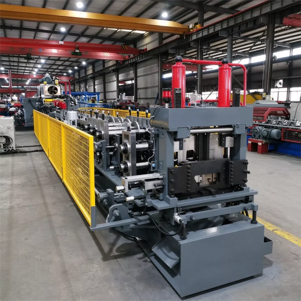
A solar farm is a steel structure before it is an electrical one. Beyond the 41 mm rails that clamp the modules, every ground-mount solar panel mounting structure table (module mounting table) is built from C and U sections with webs from 50 mm up to 250 mm, and every rack of accessories for any PV mounting system starts from small U channels. This guide covers the two section families we roll form for solar structures — the structural layer and the accessory layer — and the production lines that produce them.
Note: this page focuses on steel section specifications for PV structures. If you are looking to buy a complete racking system, or the purlin roll forming machine for solar mounting structures to manufacture these profiles, each has its own dedicated product page — the links above and below will take you there.
You can also check our purlin machine product page for detailed configuration options and factory pricing.
The Structural Layer: C and U Sections with 50–250 mm Webs
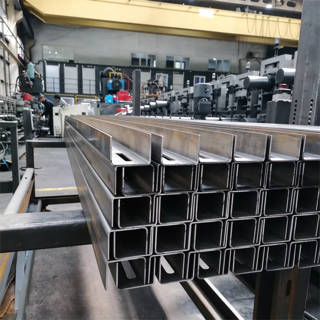
Ground-mount solar farm tables (module mounting tables) are steel structures. Their posts, secondary beams and purlins are frequently the same C and U sections used in building construction — webs from 50 to 250 mm, flanges 40–100 mm with 10–20 mm lips — formed from GI coil and punched for the attachment hardware. Unlike building purlins, these members of the solar support structure carry the array load down to the posts, so hole patterns follow the module layout rather than the roof sheet.
Why solar tables use C and U purlin sections
Module tables span metres between posts, so the load path runs through deep, stiff sections. C sections give an open face for easy attachment, and lapped continuous-span configurations extend spans where the table design calls for it. For a fabricator already running a purlin line, this is the same product family serving a second market — the difference is the hole pattern, the coating class and the tolerances the erector on site expects.
Punching options for solar structures
Solar table fabrication usually needs the holes in place before galvanizing or delivery. Three punching configurations are available: a built-in punching unit connected to the main line, an external punching unit running separately from the main line, or a hydraulic punch press — a stand-alone press selected to the customer's punching requirements (tonnage and functions per project), which can be buyer-supplied or procured by us. In all three cases the holes are punched to the customer's hole pattern, which removes a secondary drilling operation. Specify the pattern at inquiry stage — punch frame and die sets are configured to match.
The Accessory Layer: the U41/21-81 Adjustable Channel
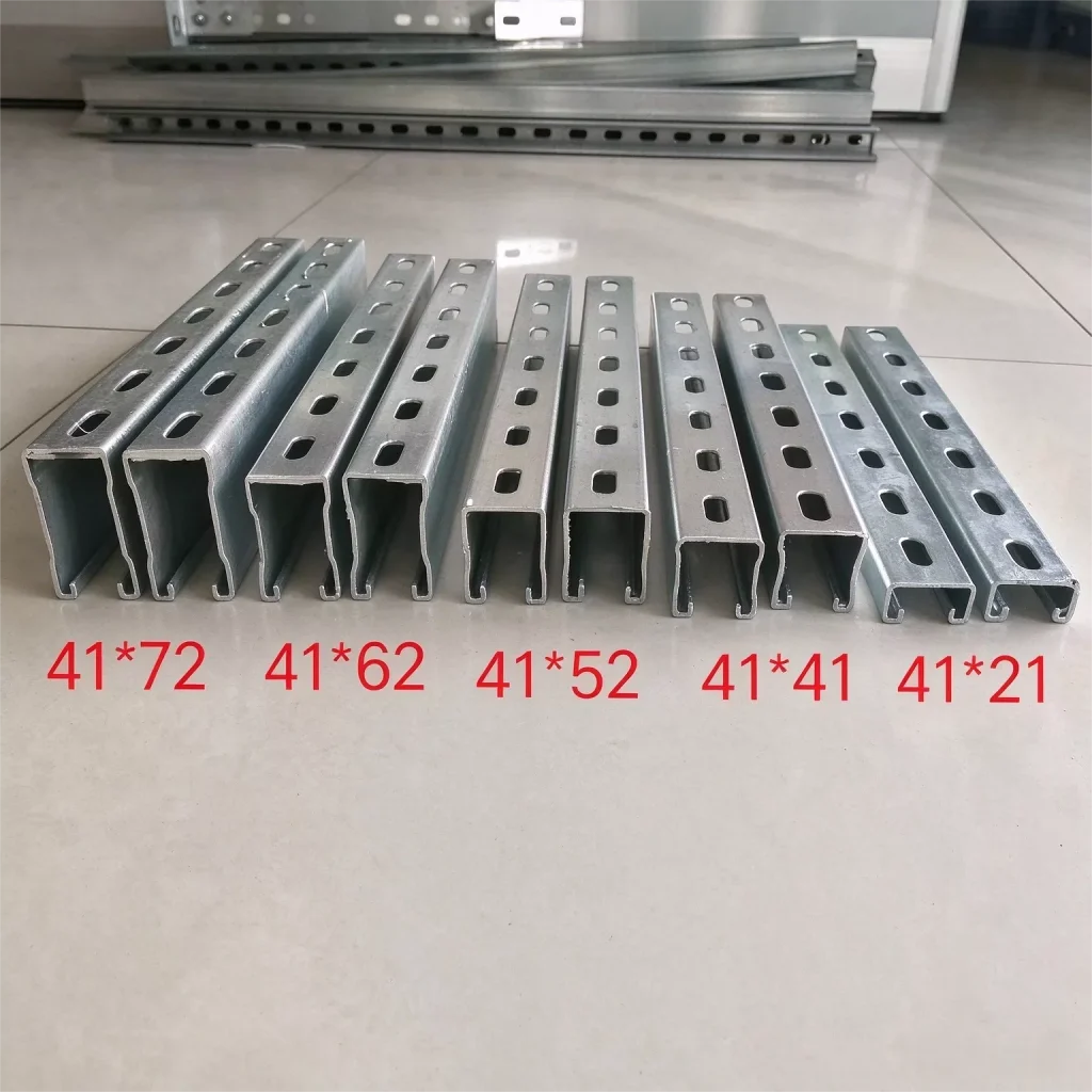
At the light end sits a dedicated production line for small PV accessories. The U41/21-81 designation stands for a U channel with a fixed 41 mm flange width and an adjustable web height from 21 mm to 81 mm. Our U41/21-81 line produces exactly that section range — the PV connection hardware family: mini rails, module clamping profiles, cable tray supports and small solar mounting bracket members. The roll forming rollers never change: web height is adjusted on the machine, and punching runs on fixed dies without any die change. Only the cutting section is changed: six shear knife sets are switched to match the profile height being produced.
One line, the whole accessory catalogue — six shear knife sets
Six shear knife sets cover the full 21–81 mm profile range, so an accessory manufacturer swaps knives between production runs, not between pieces — the rollers and the punching dies stay in place. A typical week can run 41 mm clamping profiles, then 21 mm spacers, then 81 mm cable supports — one line, one operator, one footprint. For shops supplying the full bracket range, this still replaces three or four fixed-size lines.
Materials for Both Layers
Structural C U sections are typically GI coil (ASTM A653 / EN 10346, Z275 and above) at 1.0–3.0 mm. For projects where recoating is impractical, weathering steel is an option: it forms a self-protecting oxide patina in dry atmospheric conditions, so it suits arid inland sites — but it is not recommended for coastal or salt-marsh environments, where chlorides keep the steel active and prevent the protective layer from stabilizing; those sites should use ZAM or heavy galvanizing instead. Weathering steel and thicknesses above 3.0 mm are available as custom configurations — tell us the material and gauge at inquiry. High-strength steel serves long-span table designs that need more load per member. Accessory channels run thinner, from 1.0 mm up, in GI or ZAM for coastal projects. Specify the steel grade and coating at inquiry stage — the line is engineered around them, because coating class decides roller surface finish, tooling coatings and lubricant selection.
Choosing Between the Two Layers: Where Each Section Goes
Buying the wrong type of production line is the most common mistake we see from fabricators entering the solar market, so the division is worth spelling out.
Structural layer vs accessory layer: section, machine and buyer
| Structural layer | Accessory layer | |
| Sections | C U, web 50–250 mm, flange 40–100 mm | U channels, fixed 41 mm flange width, web height 21–81 mm (adjustable on the machine) |
| Role in the PV array | Posts, secondary beams and purlins of ground-mount tables | Mini rails, clamping profiles, cable supports, brackets |
| Typical material | GI 1.0–3.0 mm; weathering steel or gauges above 3.0 mm as custom configuration — consult us | GI or ZAM, from 1.0 mm;gauges above 1.0 mm are custom configurations — please consult us. |
| Machine class | C U purlin line: frame structure, H-beam base with leveling bolts, Cr12 rollers (CNC + heat treatment), 75 mm shafts, three punching configurations | U41/21-81 line: adjustable web height, fixed punching dies, six shear knife sets |
| Who buys it | Steel structure fabricators entering the solar farm market | PV bracket and accessory manufacturers |
The two layers meet at the 41 mm module: the precision rails that clamp the modules themselves. That layer has its own machine class and is covered separately in our solar mounting rail profiles guide .
Foundations — pile posts, ground screws and hot-rolled angle brackets — are outside roll forming scope; we supply the equipment for the cold-formed sections that sit above them.
Roll Forming Lines for Solar Structure Sections
We build both platforms alongside our 41 mm solar rail lines:
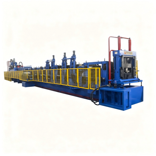
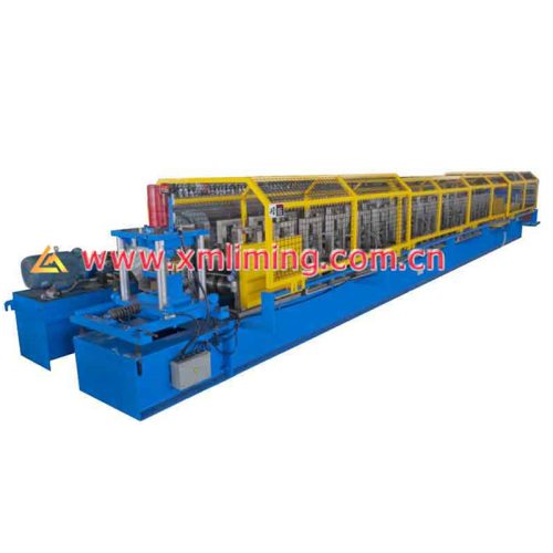
C U purlin lines for C U sections with 50–250 mm webs: frame-type structure on an H-beam base leveled with adjusting bolts; rollers in Cr12 steel, CNC-machined and heat-treated; 75 mm precision-machined shafts; three punching configurations (built-in unit, external unit, or a stand-alone punch press specified per project) for ground-mount table fabrication. Full machine parameters are listed on the solar mounting roll forming machine product page.
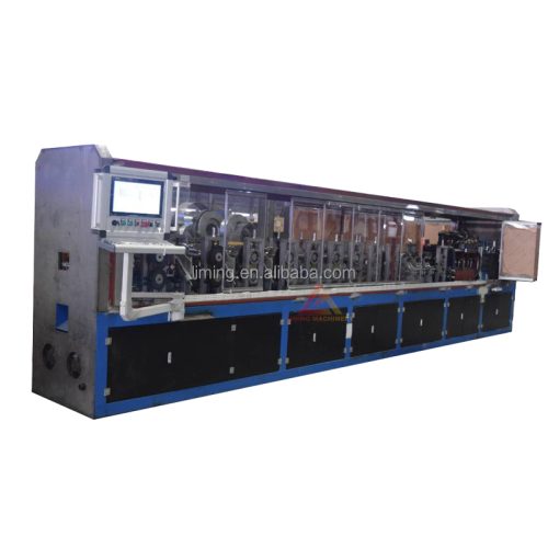
The U41/21-81 line for the accessory layer: fixed 41 mm flange width, machine-adjustable web height 21–81 mm; 27 forming stations with Cr12 heat-treated rollers on 75 mm precision shafts; 40 kW servo main drive; hydraulic flying cut-off (non-stop cutting, Cr12MoV blades) with six cutting blade sets for the 21–81 mm range; in-line feeding with servo-driven rollers and a 4-over-3 pre-leveler.
41 mm rail lines (U4141/U4121) for the precision module-mounting layer — covered in our solar mounting rail profiles guide.
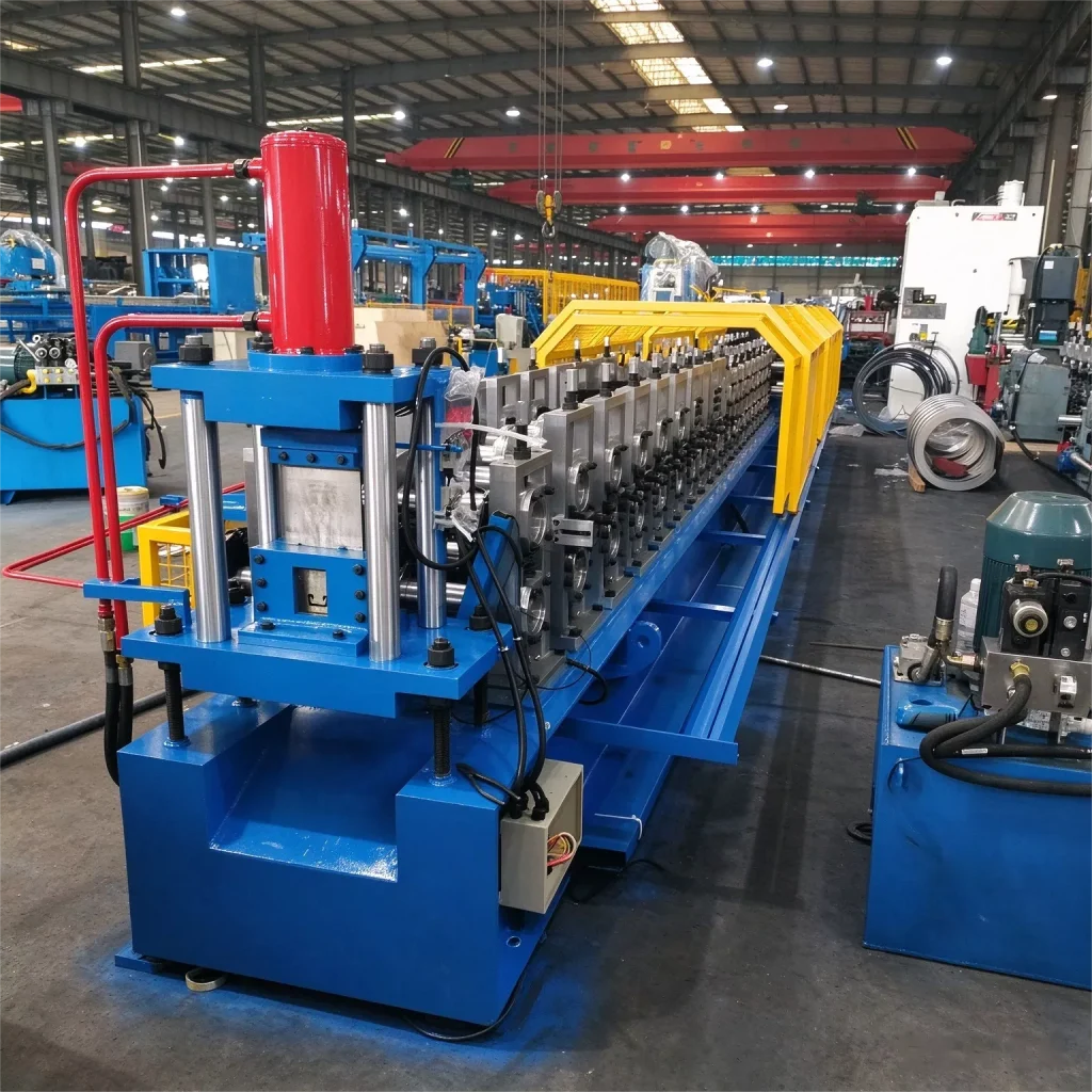
A fabricator covering a full solar farm — structure, rails and accessories — can source all three platforms from one supplier with one controls standard (Siemens PLC) across the shop floor.
Technical Specifications
Solar structure roll forming lines — key parameters
| Item | C U purlin line (structural layer) | U41/21-81 line (accessory layer) |
| Sections | C U, web 50–250 mm, flange 40–100 mm, lips 10–20 mm | U channels, fixed 41 mm flange width, web height 21–81 mm (adjustable on the machine) |
| Material | GI 1.0–3.0 mm (hot-dip galvanized coil); weathering steel or gauges above 3.0 mm as custom configuration — consult us | GI / ZAM from 1.0 mm |
| Machine construction | Frame-type structure; H-beam base leveled with adjusting bolts; rollers in Cr12 steel, CNC-machined and heat-treated; 75 mm precision-machined shafts | 27 forming stations; rollers in Cr12 steel, heat-treated; 75 mm precision-machined shafts; gear/sprocket drive |
| Feeding and leveling | Per line configuration | Auto feeding with guide section; two steps of servo-driven powered feeding rollers; 4-over-3 pre-leveler to remove coil set |
| Punching | Three punching configurations available: (1) built-in punching unit connected to the main line; (2) external punching unit running separately from the main line; (3) a stand-alone hydraulic punch press, model and tonnage selected per the customer's punching requirements — buyer-supplied or procured by us | Same three punching configurations: built-in unit, external unit, or a stand-alone hydraulic punch press selected per project (buyer-supplied or procured by us); bottom-hole punching per profile |
| Cutting | Per line configuration | Hydraulic flying cut-off, non-stop cutting with slug breaker; Cr12MoV blades, heat-treated; six cutting blade sets cover the 21–81 mm range; cutting carriage moves on line bearings, pneumatically retracted; manual-screw blade adjustment |
| Main drive and speed | Per line configuration | 40 kW servo main drive; line speed approx. 30 m/min (without punching and cutting; speed is reduced before cut-off); 15 kW hydraulic pump unit |
| Options | Punching device and die sets per hole pattern | Web height adjusted on the machine; fixed punching dies; six cutting blade sets for 21–81 mm |
FAQ
What section sizes can the C U purlin line produce for solar structures?
C and U sections with webs from 50 mm to 250 mm, flanges 40–100 mm with 10–20 mm lips, formed to the customer's drawings with inline punching for module attachment.
What is the U41/21-81 machine?
A roll forming line for U channels with a fixed 41 mm flange width and a web height adjustable from 21 mm to 81 mm on the machine: 27 forming stations, Cr12 heat-treated rollers on 75 mm shafts, a 40 kW servo main drive and approx. 30 m/min line speed. The forming rollers and punching dies never change; only the cutting section is changed — six cutting blade sets on a flying cut-off cover the profile range. One line covers clamping profiles, mini rails and cable supports.
Can one supplier cover the structure, rail and accessory layers?
Yes. We build C U purlin lines for 50–250 mm C U sections, 41 mm rail lines for U4141/U4121, and the U41/21-81 line for accessory channels — all on the same Siemens PLC standard.
What is the delivery time?
Typical delivery is about 90 working days, subject to the final machine configuration. Contact us with your section drawings for a confirmed schedule.
Planning a line for solar structure sections? Alongside our new energy roll forming machines , the dedicated solar mounting machine is specified on its product page — or contact us with your section drawings.